Closed Loop Car
Problem
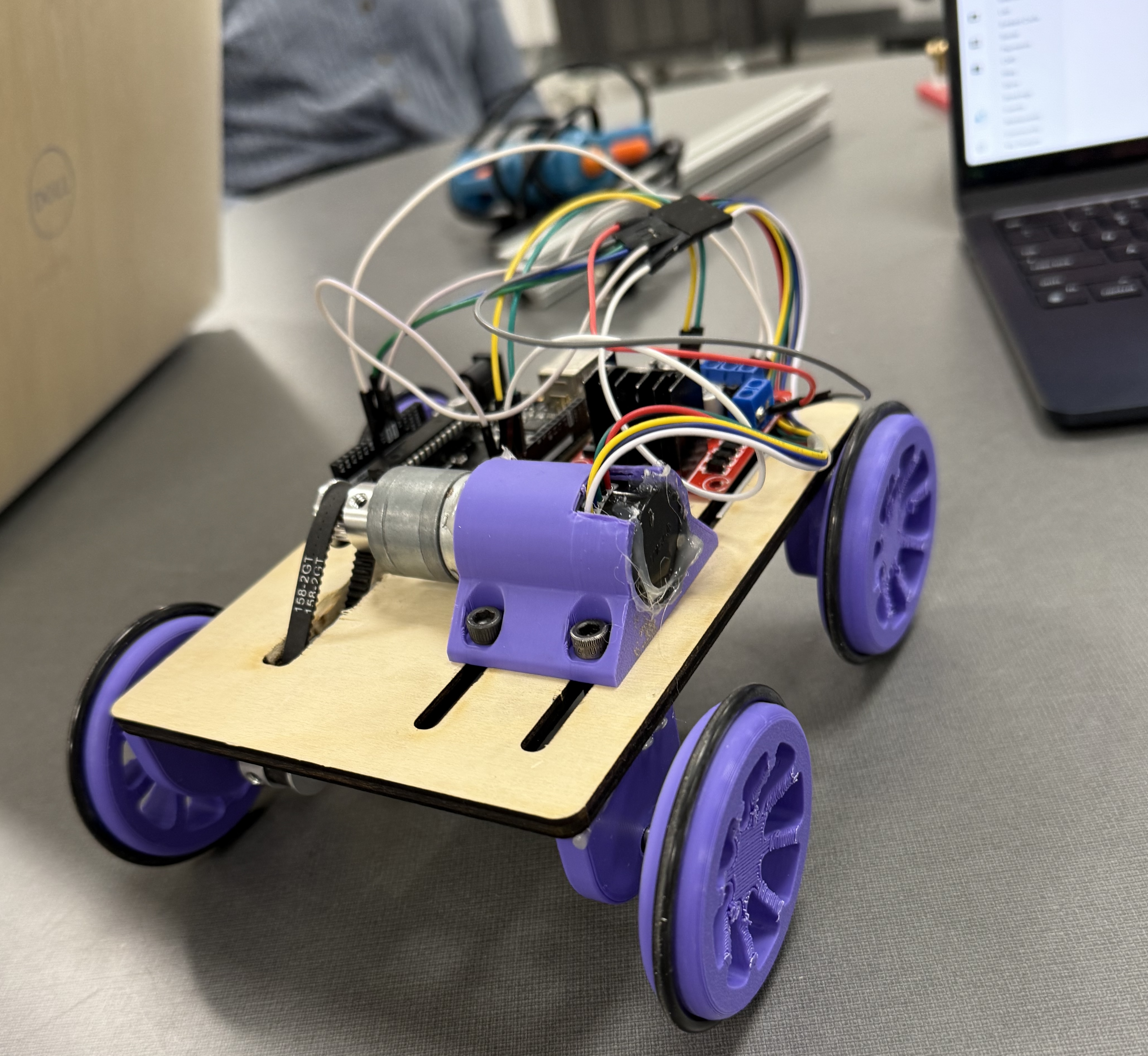
The goal of this project was to create a car that could move with a 12-inch 8020 aluminum bar on top without tipping over. This seemingly simple challenge required careful control of acceleration based on the physics of the system.
In order for the bar to not tip, the acceleration must be constant, and we determined the maximum acceleration as a function of the bar's length and width. The max acceleration equals gravity times width over length, so in our case g/12.
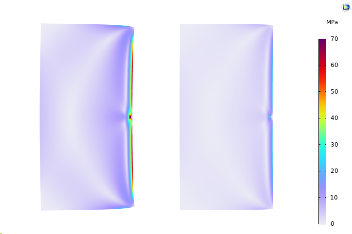
To verify that this value is realistic, we performed a SolidWorks motion analysis using a simple rectangle on a platform to minimize complexity. By giving the platform a linearly increasing acceleration and plotting the reaction force versus time, we could identify when the bar would tip (when reaction force reaches zero). The simulation yielded approximately 800 mm/s², which closely matches the theoretical value of g/12 or 0.8175 mm/s², confirming our calculations.
With the validated acceleration constraint, we created a motion study to determine the minimum time for the cart. Depending on the parameters, we achieved roughly 10-12 seconds - not as fast as the theoretical acceleration would allow, but any faster would cause the bar to tip. The bar was already showing significant oscillation at this speed.
Design Solution
My initial design concept was a simple cart with a circular hole to hold the motor. I initially planned to use gears to transfer power to the wheels, but the final design used a belt system instead.
Working as a group, we refined the design with several key improvements. We created slots in the wooden base board that allowed the motor holder to slide back and forth before being secured with screws. This enabled easy belt tensioning - a critical feature for reliable operation.
The wheels were sized large enough that the motor would not reach its RPM limit before achieving maximum acceleration. We added O-rings to the wheels to prevent slipping as the cart moved. The design also incorporated dedicated mounting space for the Arduino controller and power amplifier.
Control System
The control system uses PID (Proportional-Integral-Derivative) feedback to adjust the motor voltage based on the difference between the current speed and target speed. Using a motor with an integrated encoder, we can determine both the rotational speed and total number of rotations. Since the wheel diameter is known, calculating linear speed and distance traveled is straightforward.
Since the acceleration must be constant, we programmed the target velocity based on elapsed time. The car executes a motion profile with two accelerating phases and two decelerating phases to move forward and return to the starting position. By continuously tracking distance via the encoder, the controller knows whether to accelerate (increasing velocity at a constant rate) or decelerate at any given moment.